Adding Objects
How to place new objects onto the canvas, and the aids that help you place them precisely.
Two Ways to Start Creating an Object
Every object in Sparked Viz — from a single point to a full parametric function — starts the same way: you pick a type, then place it. There are two places to make that first pick.
From the Add Object Bar
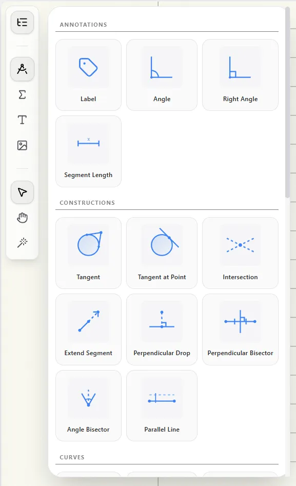
- Browse by category (Geometry, Math & Logic, Media & Text, and so on) and click the object type you want.
- Clicking a type activates the right creation tool for it — some objects place immediately, others expect a click, a drag, or a short sequence of clicks on the canvas.
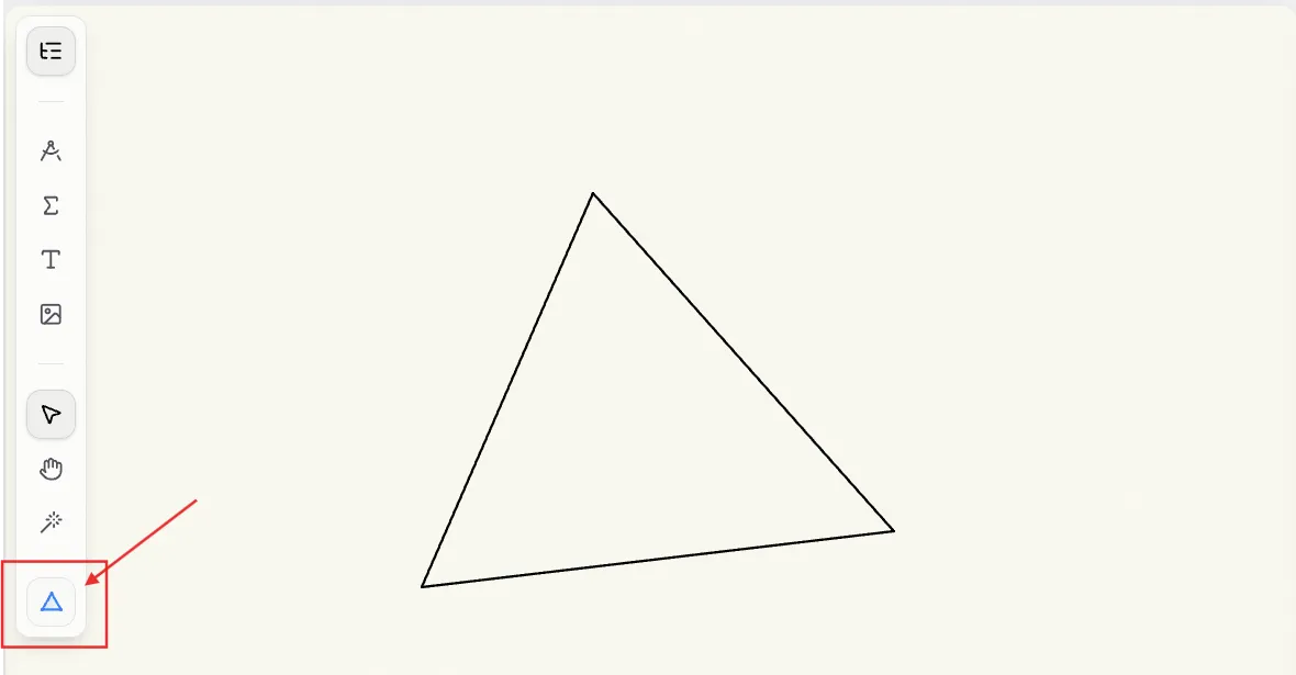
- After you place an object, a "repeat last object" button appears showing its icon — hover it for the tooltip "Create another [Object]." Click it to jump straight back into the same creation tool without reopening the category menu.
- It only remembers the single most recent type, not a history.
From the Right-Click Context Menu
- Right-click anywhere in the viewport — on empty canvas or on top of an existing object — to open a menu at your cursor.
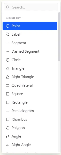
- Lists every object type across every category, with a search box at the top so you can jump straight to what you need by typing instead of browsing.
- Whatever you pick is placed starting at the point you right-clicked.
- The menu also has Copy, Duplicate, and Paste — these act on whatever is already selected, not on the object you right-clicked. Copy and Duplicate are grayed out if nothing is selected; Paste is grayed out until you've copied something, and pastes at the point you right-clicked.
The Instruction Banner
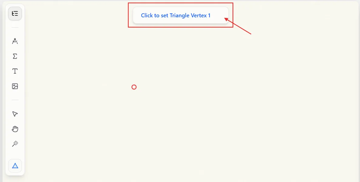

While you're creating a multi-step object — anything that needs more than one click, like a Triangle or a Perpendicular Bisector — a small banner floats at the top-center of the viewport telling you exactly what to click next. It updates after every click.
For example, creating a Triangle walks through:
- "Click to set Triangle Vertex 1"
- "Click to set Triangle Vertex 2"
- "Click to set Triangle Vertex 3"
And a Perpendicular Bisector walks through:
- "Select a Line Segment to bisect"
- "Place first endpoint on the perpendicular bisector"
- "Place second endpoint on the perpendicular bisector"
Once you've placed enough points, the banner also shows a button (such as Finish) that completes the object immediately — the same as pressing Enter — plus a Done button that backs out of creation entirely, the same as pressing Esc.
Canceling and Stepping Back (Esc / Right-Click)
Two ways to back out while you're in the middle of placing points:
- Esc cancels the whole operation and discards everything you've placed so far.
- Right-click removes just the last point you placed, so you can redo it without starting over. Right-click again to remove the point before that, and so on.
Right-click only steps back a point while a creation tool is already active. With no tool active, Right-click does something different — it opens the object-creation context menu instead (see "Two Ways to Start Creating an Object" above).
The Dynamic Input
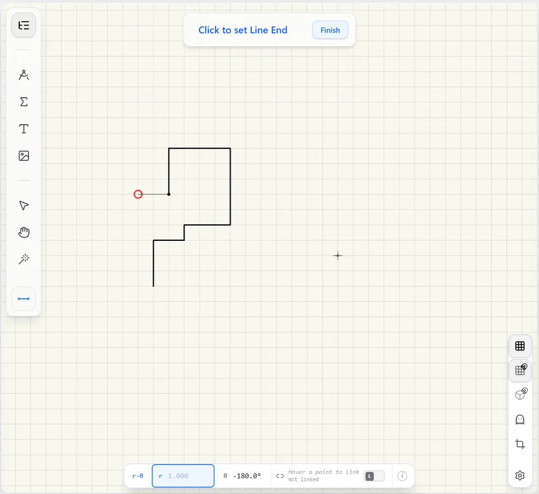
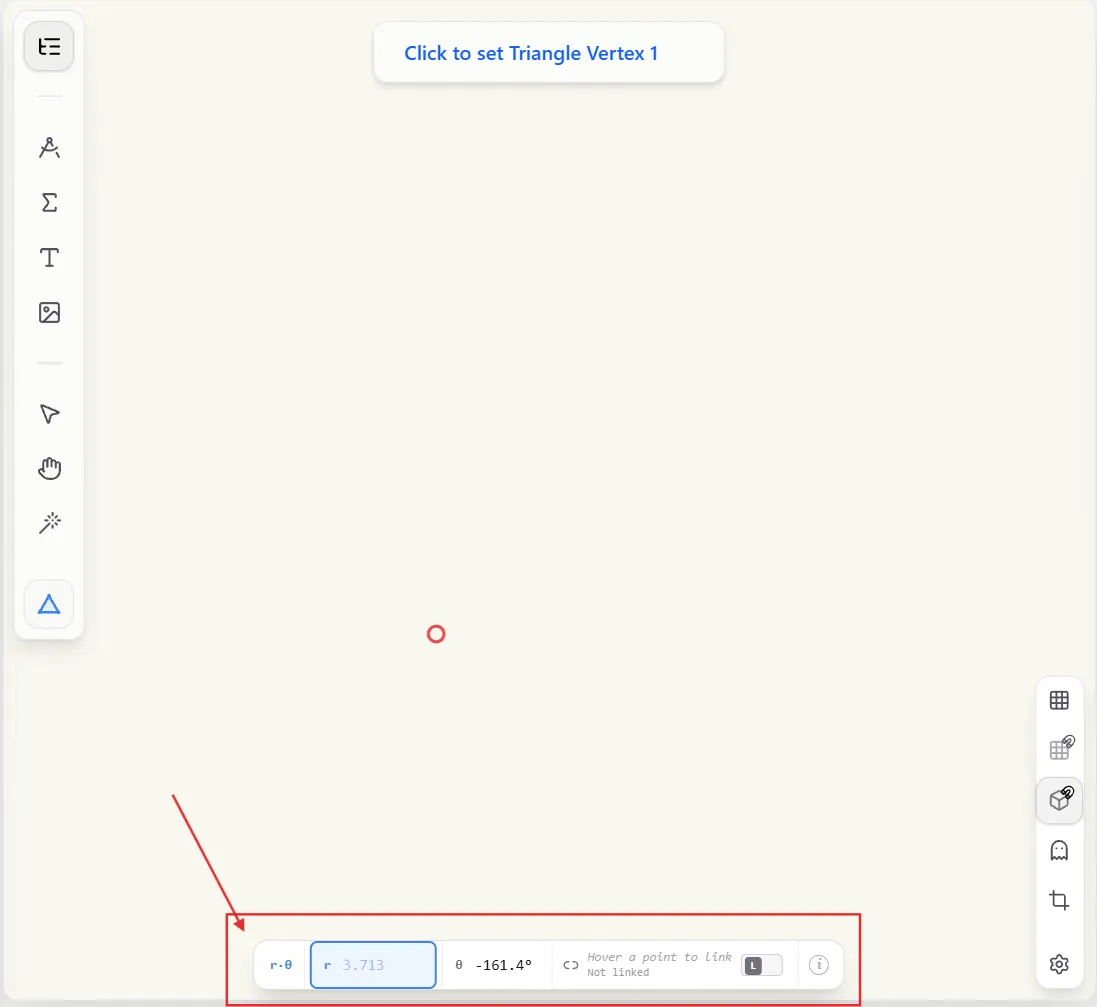
While placing a point, a small bar docked at the bottom of the viewport shows coordinate fields you can type into directly — no need to click it first. Start typing a number and it captures your keystrokes.
- It defaults to polar coordinates: r (distance) and θ (angle in degrees) from the relevant reference point.
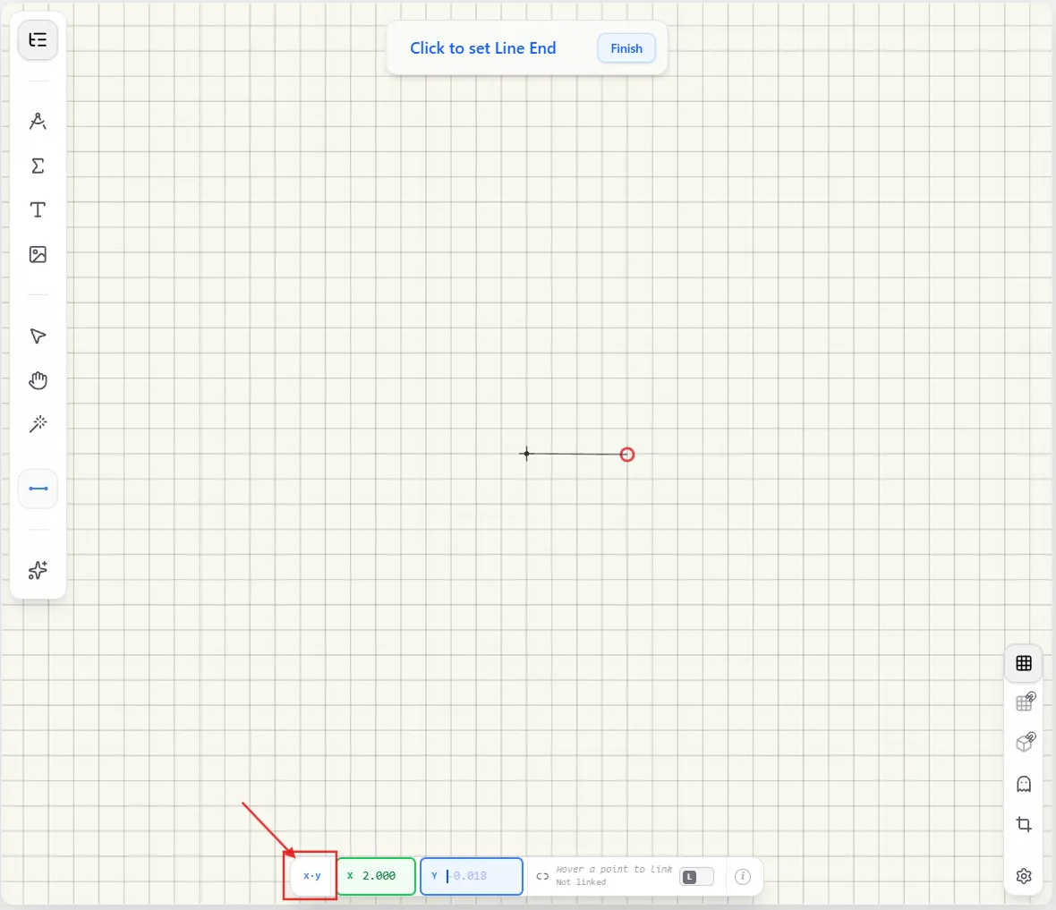
- Press Tab to switch to Cartesian X/Y coordinates instead, and Tab again to switch back.
- Use / — or just press Enter after typing a value — to move between the two fields in whichever mode you're in.
The Dynamic Input isn't available for every tool. It appears for most primitive shapes — points, segments, triangles, circles, angles, ellipses, arcs, parabolas, polygons, and more — but not for constructions that are entirely defined by another object, like Perpendicular, Tangent, Parallel Line, Extend Segment, or Intersection. Those are positioned by what you click on, not by typed coordinates.
x-y Mode vs. r-θ Mode
- r-θ mode (the default) places a point using distance and angle from a reference point: r is how far away, θ is the direction, measured in degrees. This is often the more natural way to think about angles, arcs, and rotations.
- x-y mode places a point using plain Cartesian coordinates: how far right/left (X) and up/down (Y) from the origin or reference point.
Press Tab at any time while the Dynamic Input is active to switch between them.
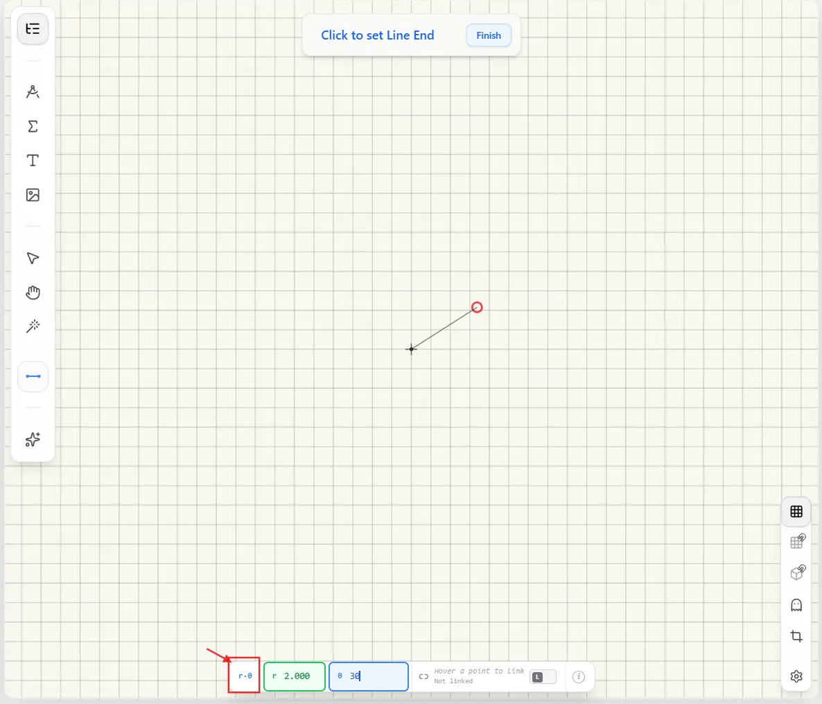
r is always measured from the current reference point — the last point you placed, or the origin if this is the first point of the sequence. θ is always measured the same way regardless of where that reference point is: 0° points due east along the world's X-axis, and positive values sweep counterclockwise — it's never relative to the direction of a segment you just drew.
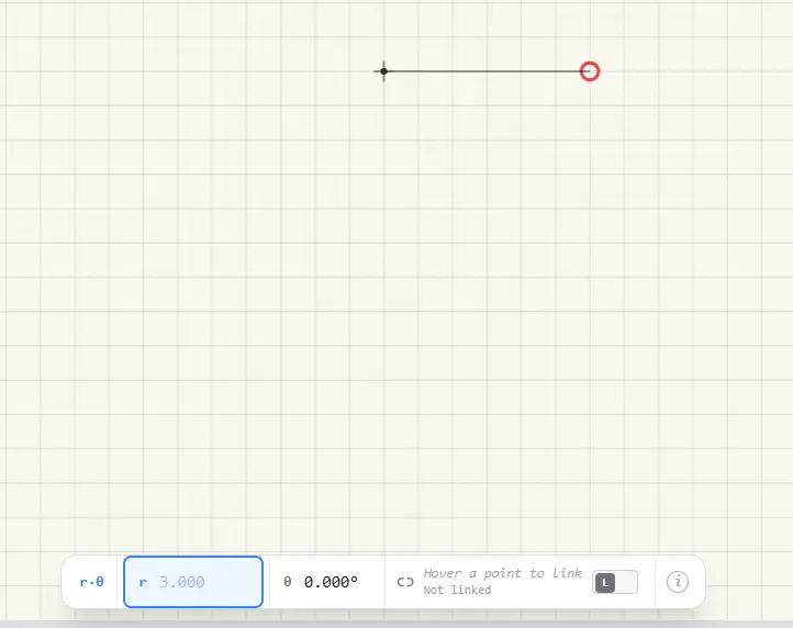
For example, r 3.000 with θ 0.0° places a point 3 units east of the reference point:
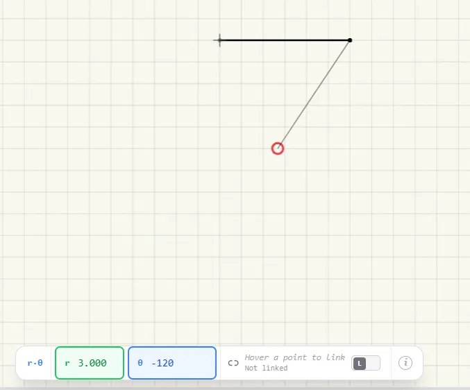
Placing the next point with r 3.000 and θ -120.0° is 3 units from that new point (now the reference point), in the -120° direction on the same world compass — not a turn relative to the segment just drawn:
Linking During Object Creation
This applies to Math2 geometry objects — points, lines, triangles, and similar constructions — while you're placing them near an existing line, curve, or point.
- Linked: the new point becomes attached to whatever geometry you're hovering over. Move that line or curve later, and the point moves with it.
- Unlinked: the point is free — it just happens to start out at that location. Moving the geometry afterward won't drag the point along.
Toggle linking with L while you're hovering something linkable, or click the link icon inside the Dynamic Input tooltip. The cursor dot's color tells you which mode is active: green for linked, blue for a plain coordinate snap, red for a free new point.
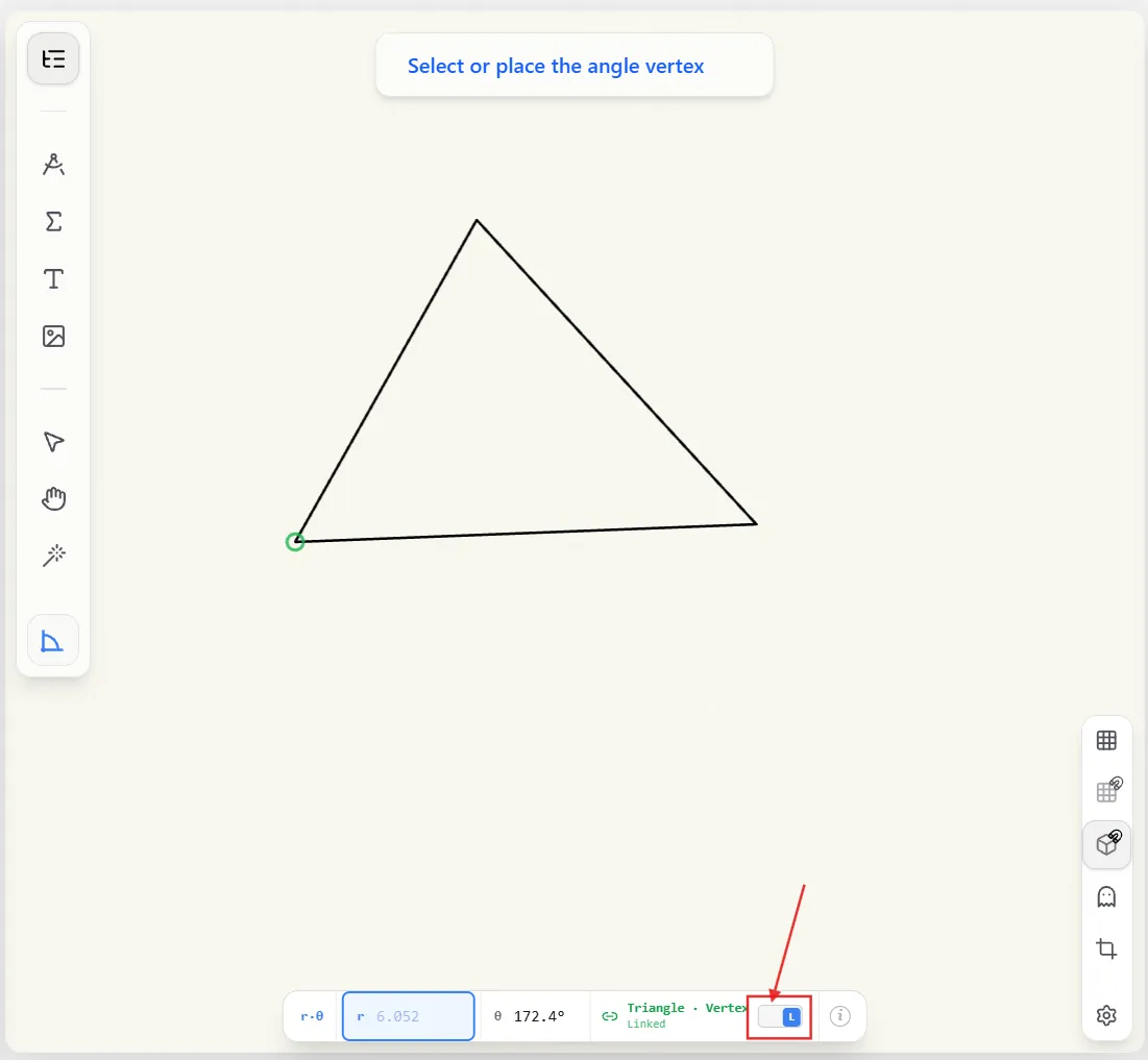

The difference shows up later, once you drag things around. Drag a linked point's geometry and everything connected to it moves too:

Drag the same setup when the point is unlinked, and the rest of the geometry stays exactly where it was:
Some tools always require a link — a Perpendicular Drop always attaches to what it drops from — and some never offer one, like a Circle's radius point.
Show Grid
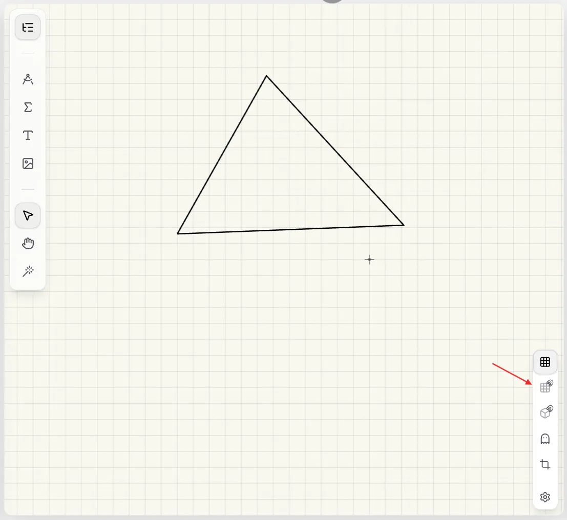
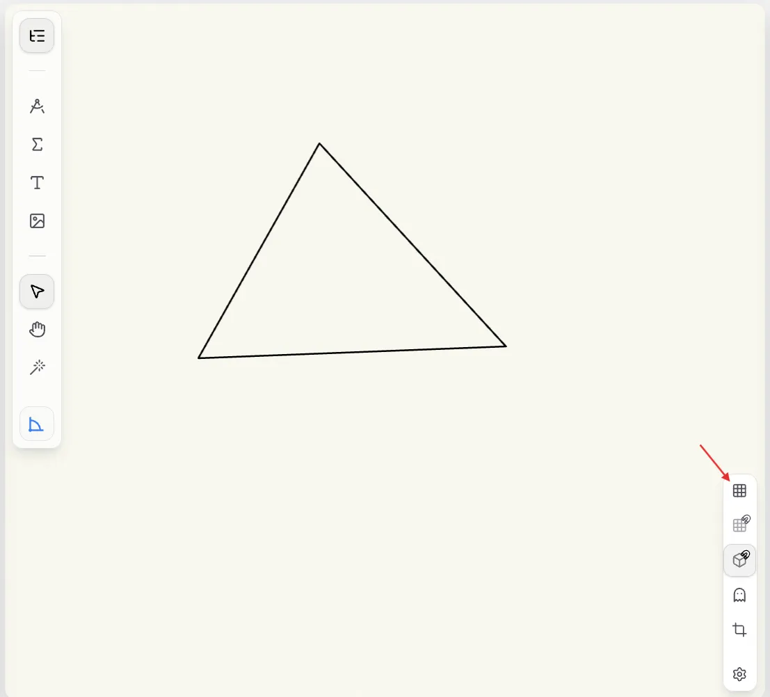
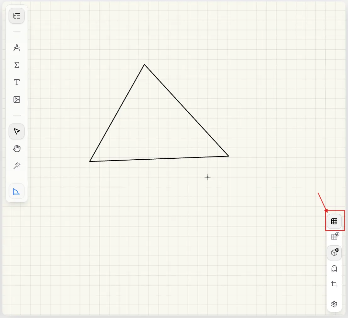
Turn on grid lines (the grid icon in the viewport controls) to see a reference grid across the canvas, useful for judging spacing and alignment by eye. This is purely visual and separate from snapping to the grid, below — you can show grid lines without snapping turned on, or snap to the grid without ever showing the lines. There's no keyboard shortcut for grid-line visibility — click the button to toggle it.
Snap to Object
With Snap to Object turned on, moving your cursor near an existing object's edge, vertex, or center pulls your next click precisely onto it — shown by a red ring at the snap point so you know exactly where you'll land.
Toggle it with F.
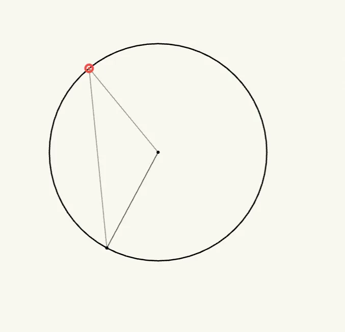
This works on curves too, not just straight edges — hovering near a circle's circumference snaps a new point precisely onto it:
Snap to Grid
With Snap to Grid turned on, your next click jumps to the nearest grid intersection instead of landing wherever your cursor happens to be — the easiest way to keep objects aligned to a consistent spacing. Unlike Snap to Object, there's no separate highlight ring; the clearest way to see it working is to also turn on grid line visibility, so you can watch the point jump between intersections as you move.
Toggle it with G.